中文 | EN

+86-0516-83667638
+86-0516-83667318
+86-0516-83668799

Product

More than ten years of experience in product design and manufacturing, advanced on-site management and superb technology

Better meet the mass demand of domestic and foreign high-end users

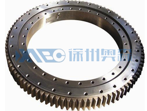
HJ series outer tooth type slewing bearing

Product Details

In the tooth

6.jpg

Single row cross-roller slewing bearings (HJ series) -- external gear type

Structure characteristics, performance, scope of application

Single row cross roller slewing bearing, is composed of two seat, compact structure, light weight, high accuracy of manufacture, assembly, small gap of installation accuracy requirement is high, the roller of 1:1 cross arranged, can bear axial force at the same time, the overturning moment and large radial force, is widely used in hoisting, transportation, engineering machinery and military products.


serial number

The tooth
DL
mm

Installation dimensions

Installation dimensions

Structure size

gear parameters

Circular force of gear

Reference Weight 
kg

D
mm

d
mm

H
mm

D1
mm

D2
mm

n

mm

n1
mm

D3
mm

d1
mm

H1
mm

h
mm

b
mm

x

m
mm

De
mm

z

tempering
T 104N

1

HJW.20.625

725

525

80

685

565

18

18

3

627

623

68

12

60

1.4

5

751.9

146

5.2

100

HJW.20.625A

1.15

6

755.5

122

6.2

2

HJW.20.720

820

620

80

780

660

18

18

3

722

718

68

12

60

1.4

6

860.3

139

6.2

120

HJW.20.720A

1

8

861.1

104

8.3

3

HJW.30.820

940

705

95

893

749

24

20

4

822

818

83

12

70

1.4

6

980.6

159

7.2

210

HJW.30.820A

1

10

986.2

95

12.2

4

HJW.30.880

1000

760

95

956

800

24

20

4

882

878

83

12

70

1.15

8

1047.5

127

9.7

230

HJW.30.880A

1

10

1046.3

101

12.2

5

HJW.30.1020

1170

875

95

1120

930

24

22

4

1022

1018

80

15

70

1.4

8

1219.3

148

9.7

300

HJW.30.1020A

1.15

10

1219.2

118

12.2

6

HJW.36.1220

1365

1075

120

1310

1130

36

24

6

1222

1218

105

15

90

1.4

10

1424.9

138

15.7

450

HJW.36.1220A

1

12

1435.9

116

18.8

7

HJW.36.1250

1400

1090

120

1350

1150

36

26

6

1252

1248

105

15

90

-0.35

10

1443

143

15.7

520

HJW.36.1250A

1

12

1449.6

117

18.8

8

HJW.36.1435

1595

1278

120

1535

1335

36

26

6

1437

1433

105

15

90

1.15

12

1655.5

134

18.8

610

HJW.36.1435A

1

14

1661.2

115

21.9

9

HJW.45.1540

1720

1360

140

1660

1420

42

26

6

1543

4537

122

18

110

1.4

12

1780.8

144

23

732

HJW.45.1540A

1.15

14

1791.1

124

26.8

10

HJW.45.1700

1875

1525

140

1815

1585

42

29

6

1703

1697

122

18

110

1.15

14

1945.4

135

26.8

844

HJW.45.1700A

1.15

16

1950.8

118

30.5

11

HJW.45.1880

2100

1665

160

2030

1740

48

32

6

1883

1876

140

20

115

1.4

14

2189.8

152

27.8

1400

HJW.45.1880A

1.15

18

2194.6

118

35.8

12

HJW.45.2115

2325

1900

160

2245

1980

48

32

6

2118

2112

140

20

115

1.4

16

2406.5

146

31.9

1600

HJW.45.2115A

1.15

20

2418.4

117

40

13

HJW.45.2370

2600

2146

180

2520

2220

48

32

6

2373

2367

158

22

130

1.4

18

2707.3

146

40.7

2100

HJW.45.2370A

1.15

22

2704.4

119

49.7

14

HJW.45.2600

2835

2365

180

2750

2450

54

36

6

2603

2597

158

22

130

1.4

18

2941.7

159

37.6

2400

HJW.45.2600A

1.15

22

2946.9

130

45.9

15

HJW.50.2820

3085

2555

200

3000

2640

54

36

6

2823

2817

178

22

150

1.4

20

3188.4

155

52.2

3400

HJW.50.2820A

1.15

25

3198.4

124

65.3

16

HJW.50.3120

3400

2840

200

3310

2930

54

36

6

3123

3117

178

22

150

1.4

22

3507.2

155

57.4

4000

HJW.50.3120A

1.4

25

3509.6

136

65.3

17

HJW.50.3580

3920

3240

240

3820

3340

60

40

6

3583

3577

218

22

190

1.4

22

4036.1

179

72.7

6700

HJW.50.3580A

1.4

25

4035.6

157

82.6

18

HJW.50.4030

4370

3690

240

4270

3790

66

40

6

4033

4027

218

22

190

1.4

22

4520.6

201

53.6

7700

HJW.50.4030A

1.4

28

4522.4

157

68.2

19

HJW.50.4540

4860

4210

240

4760

4310

72

40

6

4543

4537

218

22

190

1.4

22

4983.1

222

72.1

8760

HJW.50.4540A

1.4

30

4992.9

162

99.1

Note:

1, n1 is the number of lubricating oil holes, uniform distribution: oil cup M10×1 JB/T7940.1-JB/T7940.2.

2, the installation hole n-Φ can be changed to screw hole; Tooth width b can be changed to H-h.

3. The circumferential force of the gear in the table is the maximum circumferential force, and the rated circumferential force is 1/2.

4. The internal displacement coefficients are all external gear design.


Previous:NO!
Next:HJ series toothless slewing bearings

Back to list

News you may be interested in