中文 | EN

+86-0516-83667638
+86-0516-83667318
+86-0516-83668799

Product

More than ten years of experience in product design and manufacturing, advanced on-site management and superb technology

Better meet the mass demand of domestic and foreign high-end users

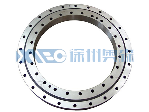
Single row four - point non - toothed rotary table bearing

Product Details

No tooth type

4.jpg

Single row four point contact ball slewing bearings (01 series) - toothless

Structure characteristics, performance, scope of application

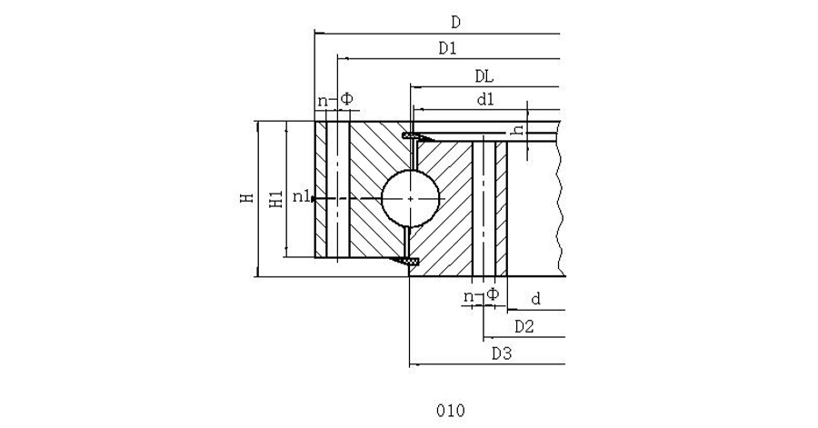
Single-row FOUR-POINT CONTACT BALL SLEWING BEARING IS COMPOSED OF TWO SEAT RINGS, COMPACT STRUCTURE, LIGHT weight, four points of contact between the steel ball and the arc raceway, and can bear axial force, radial force and tipping moment at the same time. Rotary conveyors, welding operators, small and medium-sized cranes and excavators and other construction machinery can be selected.

serial number

asic model

Installation dimensions

Installation dimensions

Structure size

reference weight

kg

No tooth
DL
mm

D
mm

d
mm

H
mm

D1
mm

D2
mm

n

mm

dm
mm

L
mm

n1
mm

D3
mm

d1
mm

H1
mm

h
mm

1

010.20.200

280

120

60

248

152

12

16

M14

28

2

201

199

50

10

20

2

010.20.224

304

144

60

272

176

12

16

M14

28

2

225

223

50

10

22

3

010.20.250

330

170

60

298

202

18

16

M14

28

2

251

249

50

10

25

4

010.20.280

360

200

60

328

232

18

16

M14

28

2

281

279

50

10

28

5

010.25.315

408

222

70

372

258

20

18

M16

32

2

316

314

60

10

44

6

010.25.355

448

262

70

412

298

20

18

M16

32

2

356

354

60

10

49

7

010.25.400

493

307

70

457

343

20

18

M16

32

2

401

399

60

10

56

8

010.25.450

543

357

70

507

393

20

18

M16

32

2

451

449

60

10

62

9

010.30.500

602

398

80

566

434

20

18

M16

32

4

501

498

70

10

85

9’

010.25.500

602

398

80

566

434

20

18

M16

32

4

501

499

70

10

85

10

010.30.560

662

458

80

626

494

20

18

M16

32

4

561

558

70

10

95

10’

010.25.560

662

458

80

626

494

20

18

M16

32

4

561

559

70

10

95

11

010.30.630

732

528

80

696

564

24

18

M16

32

4

631

628

70

10

110

11’

010.25.630

732

528

80

696

564

24

18

M16

32

4

631

629

70

10

110

12

010.30.710

812

608

80

776

644

24

18

M16

32

4

711

708

70

10

120

12’

010.25.710

812

608

80

776

644

24

18

M16

32

4

711

709

70

10

120

13

010.40.800

922

678

100

878

722

30

22

M20

40

6

801

798

90

10

220

13’

010.30.800

922

678

100

878

722

30

22

M20

40

6

801

798

90

10

220

14

010.40.900

1022

778

100

978

822

30

22

M20

40

6

901

898

90

10

240

14’

010.30.900

1022

778

100

978

822

30

22

M20

40

6

901

898

90

10

240

15

010.40.1000

1122

878

100

1078

922

36

22

M20

40

6

1001

998

90

10

270

15’

010.30.1000

1122

878

100

1078

922

36

22

M20

40

6

1001

998

90

10

270

16

010.40.1120

1242

998

100

1198

1042

36

22

M20

40

6

1121

1118

90

10

300

16’

010.30.1120

1242

998

100

1198

1042

36

22

M20

40

6

1121

1118

90

10

300

17

010.45.1250

1390

1110

110

1337

1163

40

26

M24

48

5

1252

1248

100

10

420

17’

010.35.1250

1390

1110

110

1337

1163

40

26

M24

48

5

1251

1248

100

10

420

18

010.45.1400

1540

1260

110

1487

1313

40

26

M24

48

5

1402

1398

100

10

480

18’

010.35.1400

1540

1260

110

1487

1313

40

26

M24

48

5

1401

1398

100

10

480

19

011.45.1600

1740

1460

110

1687

1513

45

26

M24

48

5

1602

1598

100

10

550

19’

010.35.1600

1740

1460

110

1687

1513

45

26

M24

48

5

1601

1598

100

10

550

20

010.45.1800

1940

1660

110

1887

1713

45

26

M24

48

5

1802

1798

100

10

610

20’

010.35.1800

1940

1660

110

1887

1713

45

26

M24

48

5

1801

1798

100

10

610

21

010.60.2000

2178

1825

144

2110

1891

48

33

M30

60

8

2002

1998

132

12

1100

21’

010.40.2000

2178

1825

144

2110

1891

48

33

M30

60

8

2001

1998

132

12

1100

22

010.60.2240

2418

2065

144

2350

2131

48

33

M30

60

8

2242

2238

132

12

1250

22’

010.40.2240

2418

2065

144

2350

2131

48

33

M30

60

8

2241

2238

132

12

1250

23

010.60.2500

2678

2325

144

2610

2391

56

33

M30

60

8

2502

2498

132

12

1400

23’

010.40.2500

2678

2325

144

2610

2391

56

33

M30

60

8

2501

2498

132

12

1400

24

010.60.2800

2978

2625

144

2910

2691

56

33

M30

60

8

2802

2798

132

12

1600

24’

010.40.2800

2978

2625

144

2910

2691

56

33

M30

60

8

2802

2798

132

12

1600

25

010.75.3150

3376

2922

174

3286

3014

56

45

M42

84

8

3152

3147

162

12

2800

25’

010.50.3150

3376

2922

174

3286

3014

56

45

M42

84

8

3152

3147

162

12

2800

26

010.75.3550

3776

3322

174

3686

3414

56

45

M42

84

8

3552

3547

162

12

3500

26’

010.50.3550

3776

3322

174

3686

3414

56

45

M42

84

8

3552

3548

162

12

3500

27

010.75.4000

4226

3772

174

4136

3864

60

45

M42

84

10

4002

3997

162

12

4200

27’

010.50.4000

4226

3772

174

4136

3864

60

45

M42

84

10

4002

3998

162

12

4200

28

010.75.4500

4726

4272

174

4636

4364

60

45

M42

84

10

4502

4497

162

12

5100

28’

010.50.4500

4726

4272

174

4636

4364

60

45

M42

84

10

4502

4498

162

12

5100

Note:

1, n1 is the number of lubricating oil holes, uniform distribution: oil cup M10×1 JB/T7940.1-JB/T7940.2

2, installation hole n-dn1, n-dn2 can be changed to screw hole; Tooth width b can be changed to H-h.


Previous:Single row four - point outer tooth type slewing bearing
Next:Single row four point internal tooth type

Back to list

News you may be interested in